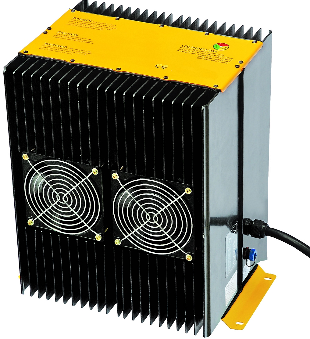
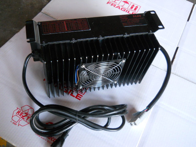
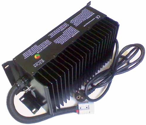
Elcon High Frequency Power Factor Controlled Chargers
Elcon High Frequency Power Factor Controlled battery chargers can charge lithium and lead acid (flooded, gel and AGM) batteries with ten user selections and can be CAN bus controlled by adding a CAN bus adapter. Two PFC 5000s can be combined to make a PFC 10000.
Click on picture to go to page:
The following Elcon High Frequency PFC chargers are available:
- PFC 5000 312V 14A
- PFC 5000 288V 15A
- PFC 5000 216V 20A
- PFC 5000 168V 24A
- PFC 5000 144V 30A
- PFC 5000 72V 56A
- PFC 4000 72V 50A
- PFC 5000 48V 80A
- PFC 1500 240V 5A
- PFC 1500 144V 8A
- PFC 1500 72V 16A
- PFC 1500 48V 25A
- PFC 1500 36V 33A
- PFC 1500 24V 40A
Frequently Asked Questions About Elcon PFC Chargers:
What are the 10 selections I can make on my Elcon PFC charger?
Elcon PFC chargers can provide 10 different 20 hour Amp Hour selections (battery sizes), or 10 different Cell Count selections (charge-to voltages) based on customer request at the time of purchase.
How do I change the selection on my charger?
When the charger is powered up, the red LED blinks from 1 to 10 times to show the current selection. To change this selection, peel off the bottom right corner of the Model Number label (nearest the end of the charger) and look through the small oval hole underneath. There should be a black plastic button (or a metal button on older chargers). Use a wooden or plastic stick to hold down the selection button while plugging the charger into AC. The green LED will start blinking slowly. Count the number of blinks (1 to 10) and release the selection button. The red LED will blink the same number of times to confirm your selection, and the charger will start charging.
How do I know which selection to choose?
With your charger you will receive a programming sheet that describes the 10 Amp Hour or Cell Count selections you have available. A selection table is also attached to the side of the charger. If your battery size has changed, you look up the closest battery size (20 hour capacity rating in Amp Hours) on the sheet and set the charger to the corresponding selection. If you are adding or deleting cells or fine tuning your final voltage, you can look up the new cell count or final voltage in the programing sheet or selection label and set the charger to the corresponding selection.
What is the best way to mount my Elcon PFC charger?
Your owners manual shows the proper orientation to mount your charger. In general, the best orientation is when the cooling fins are vertical with open space above and below them. Mounting the charger on a metal wall or frame will provide additional conductive cooling and also ground the frame. If the charger is in an enclosed area, make sure there are adequate holes in the bottom and top of the enclosed area for adequate cooling while charging. AC fans can be added to the top and bottom of the enclosure (both blowing upwards) to provide additional ventilation. Make sure the charger is not in the same area as flooded batteries to prevent corrosion due to battery acid fumes produced while charging.
What kind of batteries can be charged with a Elcon PFC charger?
Elcon chargers can charge all battery types such as lead acid (Flooded, Gel or AGM) and lithium ion (LFP and LiPoly). Every Elcon PFC charger is programmed specifically for the customer’s exact application, battery chemistry, battery capacity and environmental conditions. Elcon charging algorithms are approved by the major battery manufacturers. Please contact us below with a detailed description of the batteries you are considering or have already purchased. Elcon PFC chargers can be controlled by a Battery Management System using Enable/Disable control or CAN bus control (using a CAN bus adapter).
How do I take care of my flooded lead acid batteries?
Make sure batteries are mounted firmly in a battery box with adequate space between them for cooling. Use AC fans for cooling them while charging if necessary. Flooded batteries should have a metal pan underneath to catch any battery acid condensation or spill over. Check the water in flooded batteries at least once a month and top it off with distilled water. Make sure flooded batteries are adequately ventilated while charging and the acid fumes are directed out into open air, not into the vehicle or toward sensitive electronic equipment (including the charger). Keep flooded batteries fully charged when not in use. If after 2 or 3 years of regular use, the charger starts timing out (LED error message RGR – – – – -) during charging, the batteries may be getting too old and may need to be replaced.
How can I change the charging algorithm in my charger?
If you have changed to a different type of batteries, or have added or removed a significant number of cells, and your charger was not programmed to accommodate any cell count changes, or the change is beyond what the cell count range allows, you will need to send your charger to the address below with details about your new batteries for reprogramming.
How can I verify that my Elcon PFC charger is charging properly?
You will need a voltmeter or multimeter and a clamp-on ammeter to verify that the charger is following the charge curve that was shipped with your charger. The voltmeter should be connected across the charger DC output terminals and the clamp-on ammeter clamped on either the red or black DC output wire. If the battery pack is very low (i.e. between V1 and V2), the current will be I1 (1 second blinking red LED). Between V2 and V4, the current will be I2 (solid red LED). At V4, the voltage will stay constant while the current drops down to I3 (3 second blinking red LED). If your charge curve has a fourth (equalization) stage, the current will stay at I3 (steady or pulsing) while the voltage rises toward Um (solid or pulsing yellow LED). Once the voltage stops rising, the charger will stop charging (solid green LED). If the final stage is a float stage, the green LED will be blinking.
How can I control a Elcon PFC charger with my BMS?
We offer several different ways of controlling Elcon PFC chargers by a Battery Management System (BMS) which is used for charging lithium ion (LFP and LiPoly) batteries. The simplest way is to use the Charger Enable/Disable control on the BMS. If your BMS already has a charger enable/disable relay, the normally open contacts of the relay should be connected to the charger enable/disable wires provided by us with your charger. If your BMS only provides +12V and ground to enable/disable the charger, you must connect the coil of a small 12V relay (such as G5V-2-12V) to the +12V and ground, and connect the enable/disable wires from the charger to the normally open contacts of the relay. If your BMS has a 0-5V current control output, or you have a 0-5V potentiometer, we can program the charger with 2-5V control to vary the output current of the charger from 0% to 100%. If you have CAN bus control available on your BMS, we can program the charger for CAN bus control and add a CAN bus adapter. The method of control you wish to use must be specified at the time of order so we can program the charger accordingly.
How can I use CAN bus control with my Elcon PFC charger?
If your Elcon PFC charger has been programmed for CAN bus control and you received a CAN bus adapter with your charger, pin 1 of the adapter must be connected to CANL from your BMS and pin 2 to CANH. Also add a 120 ohm termination resistor between CANL and CANH at the CAN connector. The charger expects to receive every second a message from the BMS with CAN ID 1806E5F4 and 8 data bytes with the voltage and current requested. If the charger doesn’t receive a valid CAN message in 5 seconds, it stops charging until it receives a valid CAN message. The charger sends out every second a CAN status message with voltage, current and status information. Up to 4 chargers with CAN IDs 1806E5F4, 1806E7F4, 1806E8F4 and 1806E9F4 can be connected to the CAN bus and be controlled by one BMS, with the 120 ohm resistor only on the last charger on the bus.
What is the function of the thin green wire bundled with the DC output wires?
The thin green wire bundled with the thick red and black DC output wires with a small fast-on connector on the end is called the interlock wire and is used by some controllers to disable the vehicle while the battery is being charged. It has the full battery voltage on it when the battery is not being charged and is disconnected from everything while the battery is being charged. Most people do not use this wire if they do not have the interlock function on their controller and should cover the fast-on connector with electrical tape for safety.
What are the normal LED colors on the Elcon PFC charger?
When the Elcon PFC charger is operating normally, it will blink red 1 to 10 times when plugged into AC to indicate the Amp Hour or Cell Count selection, then blink green once and start charging. Depending on the charging algorithm programmed into your charger, there will be three or four charging stages. The first constant current stage (if the battery is very low) is fast (one second) red blinking. The main charging stage (constant current) is solid red LED. The third (constant voltage) stage is slow (three second) red blinking. The fourth (constant current or pulsing current) equalization stage (if present) will be solid or pulsing yellow. When charging ends, the LED will turn solid green. If there is float charge, the LED will be blinking green.
If the charger is programmed for CAN Bus control, it will blink red-green-red-green at the start and wait for a CAN command from the BMS with a blinking green LED. Once it receives a valid CAN command it starts charging and the red LED starts blinking.
What are the LED error messages on a Elcon PFC charger?
If there is an error condition and the charger is not charging, it will continuously display one of the following eight second error message on the external Red-Green LED. (The dash means one second).
- RG – – – – – – Wrong battery or battery voltage is too high.
- RGR – – – – – Time out. There is a time limit for each charging stage. Your batteries may be too big for the charger or too old, or the Amp Hour selection is wrong.
- RGRG – – – – Battery temperature too high. Put a cooling fan on the batteries while charging or improve their ventilation and spacing.
- RGRGR – – – AC voltage is too high or too low. Should be between 100 and 240VAC.
- RGRGRG – – Battery temperature probe is required, but is missing or defective.
- RGRGRGR – Communication error (CAN bus only).
- R – G – R – G – Battery not connected or out of specification or DC output fuse is blown (or waiting for CAN bus command).
- GR – – – – – – Charger is overheated. Unplug it and let it cool down. Put a fan on it while charging.
Can I use an extension cord with my Elcon PFC charger?
A long extension cord is not recommended. If an extension cord has to be used, make a custom extension cord that is as short as possible, and uses wires that are as thick as the AC cord on the charger (11AWG for PFC 5000, 14AWG for PFC 2500). Use a new plug and receptacle, tin the ends of the wires and make sure they are tightly screwed inside the plug and receptacle.
How can I check if the DC output fuse is blown?
If your Elcon charger LED is continuously blinking Red-Green-Red-Green-, either your battery is out of specification (too low or too high) or the battery is not connected to the charger. Make sure you can measure the full battery voltage at the charger DC output connector. (If your charger is programmed for CAN bus control, continuously blinking Red-Green-Red-Green- also means the charger is waiting for a valid CAN bus command.) If everything above checks out OK and your battery voltage is within specifications, the DC output fuse on the charger may be blown. Disconnect the charger from everything and check the continuity between the thick red (positive) DC output wire and the thin green interlock wire (with a small fast-on connector on the end) which is bundled with the DC output wires. If there is no continuity, the DC output fuse is blown and the charger needs to be sent to the address below for repair.
How can I check if the AC fuse inside the charger is OK?
If the AC fuse is OK, you will hear a faint click inside when you plug the charger into AC. Also if the charger shows any LED colors, the AC fuse is OK. The AC cooling fans will run even if the AC fuse is blown. If there are no LED colors, the charger needs to be sent to the address below for repair.